
Structures in LabVIEW
The structures in LabVIEW contain sections of graphical code. They control and determine when and how the code should be run in a virtual instrument (VI). A structure can be referred to as a graphical representation of a loop. It helps in iterating a piece of code as many times as we want.
Wish to make a career in the world of Labview? Start with Labview Training !
How to access structures in LabVIEW?
Open LabVIEW, and open the Front Panel. Click on the ‘View’ option from the top menu and select ‘Functions’. Choose the ‘Programming’ option and click on the ‘Structures’ icon. You will get a list of all the structures of LabVIEW. To use a structure, drag and drop them on to the block diagram.
Types of structures in LabVIEW
LabVIEW offers different kinds of structures that serve different purposes. Here is the list of structures that are available in LabVIEW.
- While Loop structure
- For Loop structure
- Sequence structure
- Flat sequence structure
- Stacked sequence structure
- Event structure
- Timed structure
- Diagram disable structure
- Conditional disable structure
Let’s discuss in detail each of these structures and how to implement them.
While Loop structure
The While loop structure continues to execute a programme until a stop condition is met. When a STOP button is clicked, the while loop structure is used to keep the application continuing. Until the created value equals 50 or the STOP condition is met, and the while loop structure continues to execute and generate new values.
- While loop is created as follows:

- Now Create a random number generator.

- As shown below, Create a multiply sign.

- Now Create a constant 100.

- As shown below, Create a “round of to -infinity”

- As shown below, Create a “Equal to”

- As before, create the constant 50.
- Create an indication for the “round of to – infinity” output as

- As shown below, now Wire the blocks

- Once the random number generator creates the value 50, run the application to view the results. Now the while loop should stop generating new values.

- You can view values being produced on LABVIEW’s “front panel” by using the “wait timer” that has been involved. This value is measured in milliseconds. There are 200 milliseconds here. There is a 200 seconds delay added between loop iterations.
For Loop structure
Using a for loop structure, the programme is repeated a specified number of times. N is the count terminal in the For loop, and “i” is the iteration terminal. Each time the loop runs, the value of “i” shifts from 0 to N-1.
- Just as we did with the while loop, create the for loop.
- Create a constant using input of N.
- Make an indicator of i’s output.
- A “wait” timer should be created as in a while loop.
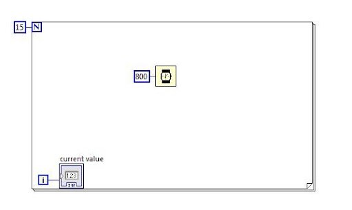
- Use LabVIEW to run the program. On LabVIEW’s front panel, you can see that the “current value” keeps rising. Till it reaches N-1, although this is 14 in this example.
- The following is another way to store the values of “i” in an array.
- Outside of the for loop, a create indicator for the output of “i.”

- Execute the LabVIEW program. As soon as the program ends, all the values will be displayed in an array on LabVIEW’s front panel.

- Graphs may also be created using arrays. Draw a block diagram similar to the below one. By navigating to the search bar and typing the names of the blocks that are shown on top of the blocks, such as “pi,” you may determine all the blocks.

- Execute the LabVIEW program and look at the graph displayed on Labview front panel.

A For loop might not execute sometimes in a VI when the condition is not met. We can change a While loop to a For loop. To do so, right-click on the border of the While loop and select the ‘Replace with For Loop’ option from the shortcut menu.
Sequence structure
A sequence structure is utilized whenever we need a program to run in a sequential manner. The order of execution is not always under your control in LabVIEW. When a subsequent computation depends on a prior one, we are confident that it will happen in the proper sequence. However, we will not be able to control the sequence of calculations when they are being done in parallel. Calculations are compelled to occur in a predetermined sequence using a sequence structure.

- Execute the program and you would see the result as below.

- The two random numbers are generated by this programme in four seconds, after which their sum is shown in two seconds.
- The Flat Sequence structure was applied in this example. When there are numerous frames, the Flat Sequence structure may consume a lot of room while still displaying all the frames (steps) in block diagram. The Stacked Sequence structure is an alternative. The frames are still sequential in the stacked sequence structure, however they are stacked one on the other. We choose the displayed frame using the Selector Label.

Labview Training
- Master Your Craft
- Lifetime LMS & Faculty Access
- 24/7 online expert support
- Real-world & Project Based Learning
Flat sequence structure
In the flat sequence structure, the block diagram contains all of the frames. The structure could require a huge amount of space if there are many frames.
A flat structure is very flexible. When a frame is added or deleted, it will resize automatically. We can change a flat sequence to a stacked sequence. If we do that, all the input terminals of the frames will be moved to the first frame of the stacked sequence. When we change the stacked sequence to a flat sequence, we have to move the wires of the first frame to their original locations, i.e., individual frames.
Top 30 labview interview questions and answers for 2020!
Stacked sequence structure
All of the frames in a stacked sequence structure are arranged sequentially but are layered on top of one another, much like a case structure.
Case structures are more commonly employed in the scenarios when the user or the program need to make a decision. These decisions are classified into two options: either true or false.
Whenever executed, just one condition will be executed i.e., true or false.
The following block diagram explains the functionalities of the case structure:
- Initially, draw the scenarios with a true value and a false value.
- This option is available in the case structure’s main menu in LabVIEW.
- Now we will calculate the log value and we need the case structure to only look for positive values.
Following is the true condition case block diagram. From the LabVIEW front end, the user will have the ability to enter a value in “X.” (that can be viewed on the block diagram’s left-hand side).

Following is the case block diagram for False condition:

In LabVIEW, run the above program entering the positive value from LabVIEW’s front end and then a negative value is entered from LabVIEW’s front end.
In this case, a true condition case structure result is shown in the LabVIEW front panel.

Then a negative value is displayed as a result within the LabVIEW’s front panel.

Event structure
- The event structure handles an event in accordance with its occurrence.
- When a particular collection of events is triggered, the event structure will run and handle that specific event as necessary.
- Sub-diagrams or event cases in an event structure are generally responsible for carrying out the events that are intended to be handled.

Subscribe to our YouTube channel to get new updates..!
Timed structure
- One or more sub diagrams/frames available in a time structure that are executed by an internal/external timing source.
- Executions take place in a sequential order. Each frame is executed only during the execution process.
Diagram disable structure
- A diagram disabled structure can be used to execute a certain piece of code in LabVIEW if the developer wants to do so.
- The developer will be able to run a specific part of the code and evaluate the outcomes by using this structure.
- Conversely, conditional disable structures can be used to do this if the developer wishes to run a specific part of code only under certain circumstances.
The steps to use a diagram disable structure are as follows:
Step 1: From the structures menu, choose the diagram disabled structure.
step 2: Place the code that you wish to run inside the disabled structure’s disable frame.
Step 3: The developer must do a right-click on the diagram’s border to disable the structure for adding more frames.
step 4: choose an option from the shortcut menu.

step 5-Only one frame at a time can be enabled.
step 6-To enable a frame then the developer need to right click on the disable structure diagram and choose the option “ Enable this subdiagram” from the shortcut menu (as shown below)

step 7: A single frame can only be activated at a time.
step 8: The developer must right-click on the diagram’s disabled structure and choose “Enable this subdiagram” from the shortcut menu in order to enable the frame.
Conditional disable structure
When we have some subdiagrams to execute depending on a condition, we can use a conditional disable structure. We can disable a subdiagram on the block diagram, so it executes based on a user-defined condition. Place a conditional disable structure on the block diagram, and add a subdiagram to it. Right-click on the border of the structure and select the ‘Edit Condition For This Subdiagram’ option.
We will get a configure condition dialog box where we can configure conditions. It also provides pre-defined symbols to configure conditions. We will have a selector label to scroll through the available subdiagrams in the structure. When we delete the structure, the subdiagrams won’t get deleted.
Labview Training
Weekday / Weekend Batches
Conclusion
In this post, we have explained in detail about all the structures in LabVIEW. Using structures will make the programming easy for developers. LabVIEW has introduced them, so the developers can execute the subdiagrams according to their needs. Try out different structures in the development of VI in LabVIEW.
Related Articles:

Stephan is the sports journalist for the Maple Grove Report.